Serial Cables IDs: Difference between revisions
Jump to navigation
Jump to search
(More precise) |
(→Weblinks: Linkfix) |
||
| Line 8: | Line 8: | ||
== Weblinks == | == Weblinks == | ||
* [https:// | * [https://www.ibm.com/resources/publications/OutputPubsDetails?PubID=SY44590203 AS/400 Service Functions], SY44-5902-03<ref>PDF page 245, Table 51, bottom line on that page displays the cable-id connected pins. See also the notes on the top of the next page.</ref> | ||
== Footnotes == | == Footnotes == | ||
Latest revision as of 13:16, 21 May 2023
| This article isn't finished yet or needs to be revised. Please keep in mind that thus it may be incomplete.
Reason: Expand, find out more about cable IDs, make table |
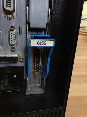
IBM Serial Cables have certain (ID) pins connected to the common ground connection pin to have the machine know what cable type is attached.
Modern PCI machines have a Mini-Centronics style connector for their serial ports, while the older, SPD based machines have D-Shell connectors. Both connectors on the machine check for the Cable-ID.
To identify a V.24, RS-232 "Modem" Cable to either a #2651 (single port), or #2609 (dual port) serial I/O-Adapter, Pins 1 and 13 need to be connected to Pin 7 (Ground) on the DB-25P connector on the machine (DCE) side. Pins 1 and 13 on the remote (DTE) side are not to be connected anywhere.
Weblinks
- AS/400 Service Functions, SY44-5902-03[1]
Footnotes
- ↑ PDF page 245, Table 51, bottom line on that page displays the cable-id connected pins. See also the notes on the top of the next page.
