Integrating LAN-less Machines into a local Token Ring
Sometimes, older, donated hardware comes without LAN I/O-adapters. Sometimes it has serial communication I/O-adapters, and Twinax, though. This article points out how to integrate such hardware into a local Token Ring network with the help of (older) Cisco hard- and software.
This description is based on a proven to work setup. Surely, there are further ideas to explore, such as bridging the ring to Ethernet for SNA communications to Ethernet connected nodes, or eliminate the ring altogether by replacing it with just a Virtual-TokenRing interface on the Cisco router.
Requirements
- AS/400, complete and functioning
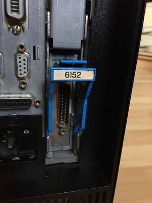
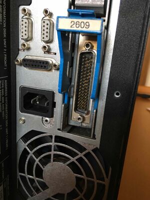
QAUTOCFGsystem variable switched to on- Local serial port with required breakouts, such as a #2609, or a #2652
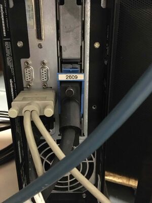
- IBM V.24 Modem Cable[1]
Note! It is of utmost importance to keep in mind that the AS/400 serial ports have sense pins, to know which kind of cable is attached. If you plug in just an ordinary PC serial cable, you’ll eventually find the succinct message in the QSYSOPR message queue, that a cable could not be found. Therefore the requirement of an IBM V.24 Modem Cable, or a self made cable providing the necessary sense pin connectivity. For this reason, you'll need to plug the DB-25F socket connector of the Cisco cable to the modem cable, and not directly to the AS/400’s port.
- Cisco 2502, 2513, 2612 or similar router model with Token Ring interface (card), and a T-Type serial interface (card), running an IOS release with the Desktop featureset (BINO3S3) for SDLC support.
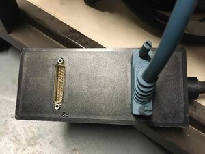
- Cisco CAB-232 FC
- Other AS/400, complete and functioning, attached and already configured to use a Token Ring LAN
QAUTOCFGsystem variable switched to on
SDLC configuration on AS/400
- After plugging everything together like pointed out above, the serial-only machine is to be configured. Type WRKHDWRSC *CMN to get a list of communication hardware, and associated ports. Example:
Resource        Type  Text
CMB01           917B  Combined function IOP
  LIN01         2609  Comm Adapter
    LIN011      2609  V.24 Port
    LIN012      2609  V.24 Port
Note! OS/400 V3 seems to not designate ports as CMN, but as LIN with three digits. Newer releases designate ports on an adapter as CMN.
- Next, the controller description (equivalent to a PU definition in VTAM) to the peer system is to be created. This needs to be done before the line description, because it is referenced there.
CRTCTLAPPC CTLD(OTHERHOST) LINKTYPE(*SDLC) MAXFRAME(1033) RMTCPNAME(REMOTEAS) STNADR(C0) NODETYPE(*CALC) TMSGRPNBR(*CALC) AUTODLTDEV(*NO) CMNRCYLMT(10 1)[2]
- Armed with this, a line description is to be created, and the controller decription referenced:
CRTLINSDLC LIND(SDLCLIN) RSRCNAME(LIN011) NRZI(*NO) LINESPEED(19200)[3] MAXFRAME(1033) DUPLEX(*FULL) LINKSPEED(19200) CTL(OTHERHOST) CMNRCYLMT(10 1)
- I suggest to run WRKCTLD and manually set the SWTDSC (press F11) to *NO. Otherwise, you’ll get a log of unneeded messages about torn down connections. It depends on the OS release if this option shows up.
- Because auto configuration is enabled, the device description (equivalent to a LU definition in VTAM) for the peer system will be created automatically at the first connection.
- REMOTEAS in the controller description is the Token Ring machine.
Configuration on the Cisco router
Assumption is that the router has already a basic configuration applied. This includes the Token Ring interface.
source-bridge ring-group 512
dlsw local-peer
!
interface Serial0/0
 bandwidth 19
 no ip address
 encapsulation sdlc
 load-interval 60
 clock rate 19200
 sdlc role prim-xid-poll
 sdlc vmac 0004.acad.5900
 sdlc address C0
 sdlc partner 0004.acad.50d5 C0
 sdlc line-speed 19200
 sdlc simultaneous full-datmode
 sdlc dlsw C0
 hold-queue 128 out
 no shutdown
!
interface TokenRing0/0
 […]
 multiring other
 source-bridge 59 1 512
Proven to work:
- Cisco 2513 with Image C2500-DOS-L, Version 12.2(29b)[4]
- Cisco 2612 with added WIC-1T, and image C2600-BINO3S3, Version 12.3(26)
Notes
sdlc vmacis the virtual MAC address the SDLC AS/400 is assigned on the Token Ring. The last byte must be 00, while IOS sets the last byte to the SDLC address being given later.sdlc addressmust be the same value as the STNADR parameter in the controller description.sdlc partnercreates an association from the already existing AS/400’s MAC address on the Token Ring to the SDLC address of the SDLC-AS/400.clock rateandsdlc line-speedmust match each other, and the LINESPEED parameter of the line description.sdlc simultaneous full-datmodecorresponds (most likely[5]) to the line description's DUPLEX(*FULL).- The
source-bridgestatement in the physical Token Ring interface gives the attached ring the number 59, designates it to the source bridge 1, and bridges traffic to the virtual ring (group) 512. multiring otherforces spanning-tree explorer packets to be sent, which greatly help with translational bridging to Ethernet (see below).
Unclear:
- How is the serial interface’s traffic redirected to the ring group 512? The group number is referenced globally, and in the Token Ring interface, which hints to the fact that you can’t use this in a complex configuration with more than one ring group, probably?
Initiation, and function verification
- On the SDLC-AS/400 vary on line and controller descriptions:
VRYCFG CFGOBJ(SDLCLIN) CFGTYPE(*LIN) STATUS(*ON)
- After a brief pause, the Cisco console should show that the serial port goes up:[6]
%LINK-3-UPDOWN: Interface Serial0/0, changed state to up
%LINEPROTO-5-UPDOWN: Line protocol on Interface Serial0/0, changed state to up
- On the SDLC-AS/400, looking into the QSYSOPR-Message Queue should show that the line has successfully been varied on, and a connection to the controller OTHERHOST has been established through SDLCLIN.
- On the Cisco Router, you should see output of
show interface ser0/0similar to the following:
Serial0/0 is up, line protocol is up
  Hardware is PowerQUICC Serial
  MTU 1500 bytes, BW 19 Kbit, DLY 20000 usec,
     reliability 255/255, txload 1/255, rxload 1/255
  Encapsulation SDLC, loopback not set
    Router link station role: PRIMARY (DCE)
    Router link station metrics:
      slow-poll not configured
      T1 (reply time out) 300 milliseconds
      N1 (max frame size) 16472 bits
      N2 (retry count) 7
      poll-pause-timer 10 milliseconds
      poll-limit-value 1
      k (windowsize) 7
      modulo 8
      sdlc vmac: 0004.ACAD.59--
  sdlc addr C0 state is CONNECT
      cls_state is CLS_IN_SESSION
      VS 5, VR 6, Remote VR 5, Current retransmit count 0
      Hold queue: 0/200 IFRAMEs 1109/1325
      TESTs 0/0 XIDs 2258/19, DMs 0/0 FRMRs 0/1
      RNRs 1/0 SNRMs 10/0 DISC/RDs 3/1 REJs 0/0
      Poll: clear, Poll count: 0, ready for poll, chain: C0/C0
  Last input never, output 00:00:00, output hang never
  Last clearing of "show interface" counters 1d17h
  Input queue: 0/75/0/0 (size/max/drops/flushes); Total output drops: 0
  Queueing strategy: fifo
  Output queue: 0/128 (size/max)
  1 minute input rate 0 bits/sec, 49 packets/sec
  1 minute output rate 0 bits/sec, 49 packets/sec
     7467200 packets input, 15548792 bytes, 0 no buffer
     Received 0 broadcasts, 0 runts, 21 giants, 0 throttles
     21 input errors, 0 CRC, 0 frame, 0 overrun, 0 ignored, 0 abort
     7468810 packets output, 15116960 bytes, 0 underruns
     0 output errors, 0 collisions, 26 interface resets
     0 output buffer failures, 0 output buffers swapped out
     10 carrier transitions
     DCD=up  DSR=up  DTR=up  RTS=up  CTS=up
- On the Cisco Router, you should see output of
show dlsw local-circuitsimilar to the following:
 key         mac-addr    sap    state        port 	rif
2197187452   0004.acad.59c0 04  CONNECTED      Se0/0 	--no rif--
                 PCEP: 82AB8B88  UCEP: 82F66B7C
          0004.acad.50d5 04  CONNECTED      To0/0 	0600.2001.03B0
                 PCEP: 82F511AC  UCEP: 82F66B7C
- On the Token Ring attached AS/400, you should see the SDLC-attached AS/400 in
WRKAPPNSTS OPTION(*LOC).
Configuration corrections
The APPC Controller on the Token Ring attached machine has been created with default values. This includes MAXFRAME being set to the default for Token Ring, aka 16393. This will result in connection instabilities, if not corrected.
- On the SDLC-AS/400 vary off line and controller descriptions:
VRYCFG CFGOBJ(SDLCLIN) CFGTYPE(*LIN) STATUS(*OFF)
- On the Token Ring-AS/400 vary off the controller description:
VRYCFG CFGOBJ(SDLCAS) CFGTYPE(*CTL) STATUS(*OFF)[7]
- Change configuration to better matching parameters:
CHGCTLAPPC CTLD(SDLCAS) MAXFRAME(1033) INLCNN(*ANS) NODETYPE(*CALC) AUTODLTDEV(*NO) CMNRCYLMT(10 1) CTLOWN(*USER)
- I suggest to run WRKCTLD and manually set the SWTDSC (press F11) to *NO. Otherwise, you'll get a log of unneeded messages about torn down connections. It depends on the OS release if this option shows up.
- Vary on configuration objects on both AS/400, starting with the Token Ring machine.
VRYCFG CFGOBJ(SDLCAS) CFGTYPE(*CTL) STATUS(*ON)
VRYCFG CFGOBJ(SDLCLIN) CFGTYPE(*LIN) STATUS(*ON)
You now should be able to enjoy a stable, albeit slow connection to your SDLC-Connected AS/400, with each and every service running over SNA.
Possible Errors
It is important that involved configuration settings are fixed to a maximum frame size of 1033, or less:
- SDLC Line Description on the serial AS/400,
- Controller Description for the APPN peer on the serial AS/400,
- Controller Description for the APPN peer on the Token Ring AS/400.
Failing to adhere will lead to connection errors when trying to transfer more data than occasional screen updates. Cisco IOS Debugging helps to find the culprit:
%PQUICC-1-TOOBIG: PQUICC(0/0), packet too big, packet size was 2059 bytes
SDLC Reset, Serial0/0 D2 CONNECT: N2 Expired (iframe(s) resent > N2)
Also important is to provide the proper remote CP-Name for the SDLC machine’s APPC controller description pointing to the Token Ring machine. Failing to do so will prevent CP-CP sessions to be established, and outgoing sessions from the SDLC machine will fail with a no path found error.
After implementing changes on the SDLC-Machine, it has been observed[8] that the Port LED on the Cisco Router blinks approximately once a second and then stays off. wrkcfgsts *lin shows that the line itself is up, but the controller for the peer system is stuck in retry pending. This is reflected in the qsysopr message queue showing a message that the remote was failing because of XID timeout. The Token Ring machine may or may not show an error in the qsysopr message queue.
The only reliable way to fix this is to IPL the SDLC machine.
Bridging to Ethernet
Cisco IOS has a builtin feature called translational bridging. It allows to bridge source routed (Token Ring) traffic to other media types, such as Ethernet via a “standard” transparent bridge configuration.
Configuration involves a "pseudo ring". This is a completely internal thing to IOS. No configuration necessary. Just make sure the ring number you use for it is unique within a multiple-rings network, no matter if virtual or real rings are involved.
There is no physical Token Ring interface required. You can see in the interface configuration above that the physical ring number 59 is just source bridged over bridge 1 (just a router-locally unique number) to the earlier defined ring-group 512:
interface TokenRing0/0
 […]
 source-bridge 59 1 512
Thus, just using source-bridge ring-group 512 should suffice, although I have not tested this.
Configuration
Create a transparent bridging configuration, tied to just an Ethernet interface:
bridge irb
!
interface FastEthernet1/0
 bridge-group 1
 bridge-group 1 spanning-disabled
The last step is to tie the existing ring-group 512 (see above) to a purely virtual pseudo-ring (256), over a source-bridge 2 (again just a router-locally unique number for transparent bridges) to the already created transparent bridge-group 1. Note that this configuration is global and not in an interface sub-configuration context.
source-bridge transparent 512 256 2 1
The translational bridge can be seen as a black box with virtual interfaces needing appropriate bridging parameters on the Ring- and Ethernet sides.
Parameters to source-bridge transparent are:
- Source-route ring group to attached to the translational bridge
- Pseudo-ring number of the translational bridge's virtual Token Ring port, one side of said "black box"
- Bridge number of the Ethernet side of the translational bridge's virtual Ethernet port, the other side of said "black box"
- Transparent bridge group, where the physical Ethernet port is a member of.
MAC addresses involved can be seen with show bridge 1 verbose.
Note! Token Ring and Ethernet use different bit orderings for MAC addresses! Thus, if you want to configure a node on the Ethernet side of affairs to connect to the "fake" MAC Token Ring address of your SDLC machine, you must bit-swap the address 0004.acad.5900.[9] The result is 0020.35b5.9a00.
For some combinations of machines exchanging packets over the bridge, establishing an adjacency after an outage doesn't reliably work. Packet debugging on the ethernet side show that packets from the Ring machinery is reaching the destination. Forcing a connection from both machines at nearly the same time sometimes works. Investigation is not completed.
See also
- Serial Cables IDs
- RS-232 Modem Cable Pinout
- Configuring X.25 link through Cisco IP network
- Configuring TCP/IP and SLIP with Cisco-Router and V3R2
Weblinks
- DLSw+ translation between SDLC and Token Ring media example, Cisco.com
- RS-232 timing signals, Wikipedia
- Serial Cable CAB-232FC, Cisco.com
- AS/400 Service Functions, SY44-5902-03[10]
- Bridging and IBM Networking Configuration Guide, Cisco IOS Release 15SY
Footnotes
- ↑ If the machine was attached to a modem in earlier times, and you obtained all the cables, all requirements are satisfied.
- ↑ Note that this is an example configuration for integrating a new machine into an existing APPN network. Thus, CTLD, and RMTCPNAME might not match the Token Ring AS/400’s settings.
- ↑ Depending on I/O-adapter and machine model, this might parameter limited to higher or lower values.
- ↑ This means, a Cisco 2502 (Token Ring and two T-type serial ports) will also work.
- ↑ There are also half-duplex and full-duplex commands to configure an interface which aren't used here.
- ↑ If you’re connected remotely, make sure you’ve set
term moni. - ↑ The name of the controller description depends on the name of the SDLC machine.
- ↑ On V3R2.
- ↑ One example is the “Windows only” BTT Canonical Address converter. I haven’t found a web-form based converter.
- ↑ PDF page 245, Table 51, bottom line on that page displays the cable-id connected pins. See also the notes on the top of the next page.
Acknowledgements
Thanks to Ben Huntsman, Alexander Huemer, and Herman van Kleef for hints and nudges to the right direction.


