Configuring X.25 link through Cisco IP network
Sometimes, older, donated hardware comes without LAN I/O-adapters. Sometimes it has serial communication I/O-adapters, though. This article points out how to network two AS/400's with the help of (older) Cisco hard- and software through the X.25 protocol, and XOT. This example does not make use of switched virtual circuits (SVC), but permanent virtual circuits (PVC).
Motivation
I wanted my 9401-P03 to be optically present on my desk instead in a dusty corner. The dusty corner had a Cisco 2513 nearby for SDLC network integration, but the new place just has Ethernet. So, another router was needed. Because this machine already generates considerable noise, a fanless router was desired.
First try was with a very old 1005. But even with the latest IOS release 12.0(28d), that model doesn't support SDLC encapsulation on its serial interface. Hence I decided to switch to a common protocol both machines understand: X.25, or Frame Relay. Using Frame Relay was not feasible, because OS/400 supports Frame Relay only with certain cabling options and IO-Adapters I don't have. Hence I chose X.25 as the last common denominator for RS-232/V.24.
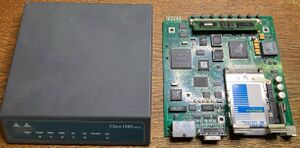
Sadly, the 1005 makes the connection fail as soon as actual transfers are attempted. I tested line speeds down to 9600 bps without success. For fault isolation, I grabbed an old Cisco 1601-R, and copied over the configuration. Connection was working at the first try with 9600 bps. I increased the line speed to 64 Kbps — the same speed the 2612 connected to the other Machine showed was possible without problems. Most notable benefit to use X.25 compared to a direct SLDC link is that serial speeds up to 64 Kbps are allowed and apparently possible, instead of just 19200 bps with SDLC.
Requirements
- Two AS/400 machines, complete and functioning
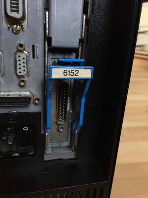
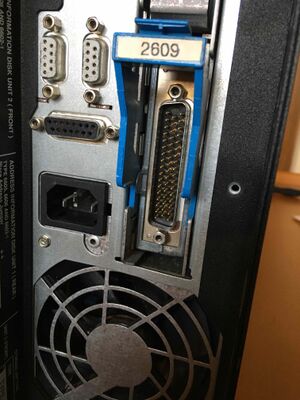
QAUTOCFGsystem variable switched to on- Local serial port with required breakouts, such as a #2609, #2652, #2720, etc.
- Matching IBM V.24 Modem Cable[1]
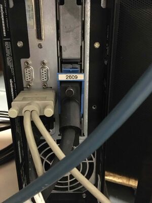
Note! It is of utmost importance to keep in mind that the AS/400 serial ports have sense pins, to know which kind of cable is attached. If you plug in just an ordinary PC serial cable, you’ll eventually find the succinct message in the QSYSOPR message queue, that a cable could not be found. Therefore the requirement of an IBM V.24 Modem Cable, or a self made cable, or adapter, providing the necessary sense pin connectivity. For this reason, you'll need to plug the DB-25F socket connector of the Cisco cable to the modem cable, and not directly to the AS/400’s port.
- Cisco 16xx, 26xx or similar router model with T-Type serial interface (card),
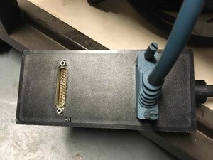
- Cisco CAB-232 FC,
- Router LAN ports configured so they can reach each other via IP.
The basic network topology is symmetric. Both AS/400s are connected to their respective Cisco routers through their serial port, and both Cisco routers are connected to each other with some LAN technology, presumably Ethernet.
Fiona → Cisco 1601-R (192.168.1.97) → Cisco 2612 (192.168.1.5) → Nibbler
Configuration
Assumption is that the routers already have a basic configuration applied.
After plugging everything together like pointed out above, obtain the resource names of the serial ports. Type wrkhdwrsc *cmn to get a list of communication hardware, and associated ports. Example:
Resource        Type  Text
CMB01           917B  Combined function IOP
  LIN01         2609  Comm Adapter
    LIN011      2609  V.24 Port
    LIN012      2609  V.24 Port
Note! OS/400 V3 seems to not designate ports as CMN, but as LIN with three digits. Newer releases designate ports on an adapter as CMN.
After you have created the line description, run dsplind x25line to find the generated Exchange-ID.
Here is a table to help configuring what, where, and in which order.
| Configuration | Cisco 1601-R (192.168.1.97) | Cisco 2612 (192.168.1.5) |
|---|---|---|
| Cisco IOS |
x25 routing interface Serial0 description Fiona LIN011 encapsulation x25 dce x25 modulo 128 x25 ltc 100 x25 pvc 6 xot 192.168.1.5 interface Serial 0/1 pvc 5 packetsize 512 512 clockrate 64000 interface Ethernet0 ip address 192.168.1.97 255.255.255.0 |
x25 routing interface Serial0/1 description Nibbler CMN01 encapsulation x25 dce load-interval 60 x25 modulo 128 x25 ltc 100 x25 pvc 5 xot 192.168.1.97 interface Serial 0 pvc 6 packetsize 512 512 clock rate 64000 interface FastEthernet1/0 ip address 192.168.1.5 255.255.255.0 |
| Fiona (V3R2) | Nibbler (V4R5) | |
| Serial resource | LIN011 | CMN01 |
| Line description | crtlinx25 lind(x25line) rsrcname(lin011) lglchle((006 *pvc)) netadr(00000000000000) cnninit(*local) interface(*rs232v24) linespeed(19200) dftpktsize(512) modulus(128) adrinsert(*no) linkspeed(64000) cmnrcylmt(1 10)
|
crtlinx25 lind(x25line) rsrcname(cmn01) lglchle((005 *pvc)) netadr(00000000000000) cnninit(*local) interface(*rs232v24) linespeed(19200) dftpktsize(512) modulus(128) adrinsert(*no) linkspeed(64000) cmnrcylmt(1 10)
|
| Exchange-ID | 05608945 | 05641700 |
| Controller description | crtctlappc ctld(nibbler) linktype(*x25) line(x25line) maxframe(512) rmtcpname(nibbler) exchid(05641700) netlvl(1984) lglchlid(006) nodetype(*calc) tmsgrpnbr(*calc) autodltdev(*no) cmnrcylmt(10 1)
|
crtctlappc ctld(fiona) linktype(*x25) line(x25line) maxframe(512) rmtcpname(fiona) exchid(05608945) netlvl(1984) lglchlid(005) nodetype(*calc) tmsgrpnbr(*calc) autodltdev(*no) cmnrcylmt(10 1)
|
Notes
- If you change the serial encapsulation value, all X.25 related configuration is discarded!
- The PVC-ID for Cisco IOS is a decimal value, and for OS/400, it's a hex value!
- You can use the same PVC on both sides.
- You cannot create the line description with the full speed outright due to error CPD26DC (Maximum line speed for RS-232/V.24 is 19200 bps.). Create the line with
linespeed(19200), and edit the lind again, setting the desired speed of 64 kbps.
Proven to work:
- Cisco 2612 with added WIC-1T, and image C2600-BINO3S3, Version 12.3(26)
- Cisco 1601-R, and image C1600-BNR2SY, Version 12.3(26)
When one side is powered down, the other side frequently posts error messages to the qsysopr message queue and problem reporting facility.
Initiation, and function verification
Turn on debugging on the Cisco routers:
term moni
debug x25
Run wrkcfgsts *lin x25line and use the interactive screen to vary on the line on both sides. You should see the lines coming up.
%LINK-3-UPDOWN: Interface Serial0/0, changed state to up
%LINEPROTO-5-UPDOWN: Line protocol on Interface Serial0/0, changed state to up
On the Cisco Router(s), you should see output of show int ser0/1 similar to the following:
Serial0/1 is up, line protocol is up
  Hardware is PowerQUICC Serial
  Description: Nibbler CMN01
  MTU 1500 bytes, BW 19200 Kbit, DLY 20000 usec,
     reliability 255/255, txload 1/255, rxload 1/255
  Encapsulation X25, loopback not set
  X.25 DCE, version 1984, address <none>, state R1, modulo 128, timer 0
      Defaults: idle VC timeout 0
        cisco encapsulation
        input/output window sizes 2/2, packet sizes 128/128
      Timers: T10 60, T11 180, T12 60, T13 60
      Channels: Incoming-only none, Two-way 100-1024, Outgoing-only none
      RESTARTs 32/0 CALLs 0+0/0+0/0+0 DIAGs 34/0
  LAPB DCE, state CONNECT, modulo 8, k 7, N1 12056, N2 20
      T1 3000, T2 0, interface outage (partial T3) 0, T4 0
      VS 6, VR 4, tx NR 4, Remote VR 6, Retransmissions 0
      Queues: U/S frames 0, I frames 0, unack. 0, reTx 0
      IFRAMEs 1664/1953 RNRs 0/0 REJs 0/0 SABM/Es 55/0 FRMRs 0/0 DISCs 0/24
  Last input never, output 00:50:34, output hang never
  Last clearing of "show interface" counters 23:57:07
  Input queue: 0/75/0/0 (size/max/drops/flushes); Total output drops: 0
  Queueing strategy: fifo
  Output queue: 0/40 (size/max)
  1 minute input rate 0 bits/sec, 0 packets/sec
  1 minute output rate 0 bits/sec, 0 packets/sec
     3654 packets input, 76438 bytes, 0 no buffer
     Received 0 broadcasts, 0 runts, 0 giants, 0 throttles
     29 input errors, 0 CRC, 29 frame, 0 overrun, 0 ignored, 0 abort
     3526 packets output, 81439 bytes, 0 underruns
     0 output errors, 0 collisions, 917 interface resets
     0 output buffer failures, 0 output buffers swapped out
     51 carrier transitions
     DCD=up  DSR=up  DTR=up  RTS=up  CTS=up
See also
- Serial Cables IDs
- RS-232 Modem Cable Pinout
- Integrating LAN-less Machines into a local Token Ring
- Configuring TCP/IP and SLIP with Cisco-Router and V3R2
- Serial networking scenarios with Cisco-Routers
Weblinks
- Configuring X.25 and LAPB on Cisco IOS, Faculty of Physics and Applied Computer Science Poland[2]
- X.25 Network Support
- RS-232 timing signals, Wikipedia
- Serial Cable CAB-232FC, Cisco.com
- AS/400 Service Functions, SY44-5902-03[3]
Footnotes
- ↑ If the machine was attached to a modem in earlier times, and you obtained all the cables, all requirements are satisfied.
- ↑ Very old documentation linked intentionally. Note: The configuration option tunnel was renamed to xot in newer IOS releases.
- ↑ PDF page 245, Table 51, bottom line on that page displays the cable-id connected pins. See also the notes on the top of the next page.
